

Waveplates introduce a controlled phase delay between orthogonal polarization components. The reference range distinguishes multiple-order, low-order, zero-order, achromatic and dual-wavelength constructions, including their mounting and bonding options.
Properties, applications and specifications
Birefringent waveplates and polarization rotators control or analyze polarization. High-energy quartz reference configurations include 90° rotators, multiple-order and compound zero-order waveplates, and Nd:YAG dual-wavelength options. The stated common wavelength range is 193 – 1550 nm. Design variables include retardance, order, wavelength, diameter and ring or air-spaced mounting.
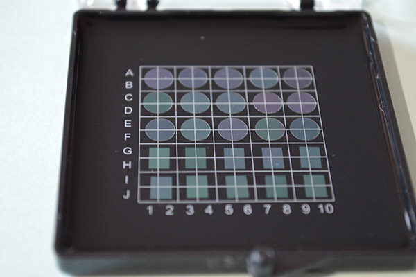
Reference options include quartz waveplates with custom retardation for use at wavelengths from 193 to 2100 nm, and with special shapes in diameters up to 2 inches. This includes compound zero-order waveplates, multiple-order waveplates for single or dual wavelength operation, as well as low-order waveplates for applications where a large field of view or high stability with wavelength and temperature variation is required. Depending on the laser damage threshold, environmental and cost constraints, compound waveplates may be cemented, optically contacted, or air-spaced. The reference range quartz polarization rotators can also be customized for the specific wavelength, rotation angle, or size.
Quartz-retarder reference specifications include low transmitted wavefront error, controlled parallelism and retardation, and 10 – 5 surface quality. Low-loss antireflection coatings support high-energy operation. Tolerances may be adapted for UV wavelengths, larger apertures or different system requirements.
Zero-order mica waveplates are another option for low-power visible and near-infrared applications.
Capabilities
|
|
Standard & Semi-custom
|
Additional Custom Options
|
|
Types
|
λ/2 & λ/4 Multiple order waveplates
λ/2 & λ/4 Compound zero waveplates
Dual wavelength waveplates
90° Polarization rotators
|
Custom retardations & wavelengths
Custom retardation angles
Low-order quartz waveplates
Mica true zero-order waveplates, bare or laminated
|
|
Materials
|
Crystal quartz
|
Mica
|
|
Dimensions
|
Waveplates: 12.7 to 50.8 mm
Rotators: 12.7 mm |
5.0 to 50.8 mm
|
|
Wavelengths
|
Waveplates: 193 - 1550 nm
Polarization rotators: 532, 1064 nm |
Waveplates: 193 - 2020 nm
Polarization rotators: 193 - 1550 nm |
|
Coatings
|
Narrowband V-coat AR
Dual-wavelength AR (532/1064 nm)
|
Other wavelength AR (193 - 2100 nm)
Lower reflectivity AR
|
|
Construction
|
Ring mounted
Optically contacted
Air-spaced mounted
|
Custom ring mounted
|
|
Quality
|
Laser quality
|
See manufacturing tolerances below
|
Quartz Waveplate Manufacturing Capabilities**
|
Surface Tolerances
|
Precision
|
Laser Quality
|
High Precision
|
|
Surface quality (scratch - dig)
|
20 - 10
|
10 - 5
|
5 - 2
|
|
Surface roughness (Å, RMS)
|
10
|
7
|
3 - 5
|
|
Transmitted Wavefront Error
(waves, P-V @ 633 nm) |
λ/2
|
λ/10
|
λ/25
|
|
Parallelism
|
≤ 2 arc sec
|
≤ 0.5 arc sec
|
|
|
Retardance Tolerance
|
λ/50 @ 23°C
|
λ/200 @ 23°C
|
λ/500 @ 23°C
|
|
Dimensional Tolerances
|
Commercial
|
Precision
|
High Precision
|
|
Diameter (mm)
|
+0.000 / -0.250
|
+0.000 / -0.100
|
+0.000 / -0.015
|
|
Clear aperture (%)
|
≥ 85%
|
≥ 90%
|
≥ 95%
|
Quartz Rotator Manufacturing Capabilities**
|
Surface Tolerances
|
Precision
|
Laser Quality
|
High Precision
|
|
Surface quality (scratch - dig)
|
40 - 20
|
10 - 5
|
5 - 2
|
|
Surface roughness (Å, RMS)
|
10
|
7
|
3 - 5
|
|
Transmitted Wavefront Error
(waves, P-V @ 633 nm) |
λ/2 to λ/4
|
λ/6 to λ/10*
|
λ/25
|
|
Parallelism
|
≤ 1 arc sec
|
≤ 0.5 arc sec
|
|
|
Rotation angle
|
|
± 0.5° at 23°C
|
|
|
Dimensional Tolerances
|
Commercial
|
Precision
|
High Precision
|
|
Diameter (mm)
|
+0.000 / -0.250
|
+0.000 / -0.100
|
+0.000 / -0.010
|
|
Clear aperture (%)
|
≥ 85%
|
≥ 90%
|
≥ 95%
|
Waveplates (retardation plates or phase shifters) are made from materials which exhibit birefringence. The velocities of the extraordinary and ordinary rays through the birefringent material varies inversely with their refractive indices. This difference in velocities gives rise to a phase difference when the two beams recombine. In the case of an incident linearly polarized beam this is given by α=2πd(neno)/λ, where α is phase difference; d is thickness of waveplate; ne,no are refractive indices of extraordinary and ordinary rays respectively; λ is wavelength. At any specific wavelength the phase difference is governed by the thickness of the retarder.
λ/2 Waveplate
The thickness of a half waveplate is such that the phase difference is 1/2-wavelength (λ/2,true zero order) or certain multiple of 1/2-wavelength [(2n+1)λ/2,multiple order].
A linearly polarized beam incident on a half waveplate emerges as a linearly polarized beam but rotated such that its angle to the optical axis is twice that of the incident beam. Therefore, half-waveplates can be used as continuously adjustable polarization rotators. Half-waveplates are used to rotate the plane of polarization, electro-optic modulation and as a variable ratio beamsplitter when used in conjunction with a polarization cube.
λ/4 Waveplate
The thickness of the quarter waveplate is such that the phase difference is 1/4 wavelength (λ/ 4,true zero order) or certain multiple of 1/4 wavelength [(2n+1)λ/4,multiple order].
If the angle θ (between the electric field vector of the incident linearly polarized beam and the retarder principal plane) of the quarter-waveplate is 45°, the emergent beam is circularly polarized. When a quarter waveplate is double passed, i.e. by mirror reflection, it acts as a half waveplates and rotates the plane of polarization to a certain angle. Quarter waveplate are used in creating circular polarization from linear or linear polarization from circular, ellipsometry, optical pumping, suppressing unwanted reflection and optical isolation
|
Waveplate
|
Part #
|
(λ/100 Bandwidth)λ/2@532nm
|
Acceptance Angle
|
Plates
|
Damage Threshold
|
|
|
Multi-order Waveplate(Quartz)
|
WPMXXXX
|
0.29nm
(T=0.9686nm) |
Low
|
Single
|
1GW/cm2
|
|
|
Low-order
Waveplate (Quartz) |
WPLXXXX
|
0.92nm
(T=0.3036mm) |
Medium
|
Single
|
1GW/cm2
|
|
|
Zero-order Waveplate
(Quartz) |
Optically
Contracted |
WPOXXXX
|
19.22nm |
Low
|
Double
(Optical Contacted) |
~200 MW/cm2
|
|
Air-spaced
|
WPAXXXX
|
19.22nm
(△T=0.0145mm) |
Low
|
Double
(Air Contacted) |
~500 MW/cm2
|
|
|
Cemented
|
WPCXXXX
|
19.22nm
(△T=0.0145mm) |
Low
|
Double Cemented
(Epoxy) |
~100 MW/cm2
|
|
|
Achromatic Waveplate
(Quartz) |
WPBXXXX
|
200nm
|
Low
|
Double
(Optical Contacted or Air Contacted) |
~10MW/cm2
|
|
|
True Zero-order Waveplate
|
High Power Waveplate
|
WPHXXXX
|
19.22nm
(T=0.0145mm) |
High
|
Double
(Optical Bonding) |
>1GW/cm2
|
|
Cemented
|
WPFXXXX
|
19.22nm
(T=0.0145mm) |
High
|
Double
(CementedContacted) |
~10MW/cm2
|
|
|
Single Plate
|
WPSXXXX
|
19.22nm
(T=0.0145mm) |
High
|
Single
|
>1GW/cm2
|
|
|
Single Plate
(Quartz) with BK7 Holder |
WPQXXXX
|
19.22nm
(T=0.0145mm) |
High
|
Single
(BK7 Ring as Holder) |
>1GW/cm2
|
|
|
DoubleWavelength Waveplate (Quartz)
|
WPDXXXX
|
Very Small
|
Low
|
Single
|
1GW/cm2
|
|
|
Fresnal Rhomb Retarder
|
FRRXXXX
|
Broadband
|
Medium
|
Single or Double (Optical Contact or Cemented)
|
500MW/cm2
|
|
|
Polarization Rotators(Quartz)
|
WPRXXXX
|
20nm
|
High
|
Single
|
1GW/cm2
|
|
|
IR Waveplate
|
WPSXXX-M
|
|
High
|
Single
|
>1GW/cm2
|
|
POLARIZATION ROTATORS
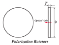
Polarization roators offer 45° to 90°rotation at a number of common laser wavelengths.The optical axis in apolarization rotator is perpendicular to the polished face.The result is that the orientation of in put linearly polarized light is rotated as it propagates through the device.
Specifications
•Wide Angle Acceptance
•Better Temperature Bandwidth
•Wide Wavelength Bandwidth
•AR Coated,R<0.2%
Standard Wavelength:532nm,632.8nm,1064nm
Reference product configurations
|
Quarter Waveplate P/ N#
|
Diameter(mm)
|
Rotation
|
|
WPR4512
|
12.7
|
45°
|
|
WPR4515
|
15.0
|
45°
|
|
WPR4520
|
20.0
|
45°
|
|
WPR4525
|
25.4
|
45°
|
|
WPR9012
|
12.7
|
90°
|
|
WPR9015
|
15.0
|
90°
|
|
WPR9020
|
20.0
|
90°
|
|
WPR9025
|
25.4
|
90°
|
HIGH POWER WAVEPLATE
Features
•True Zero Order Wavepalte
•Epoxy Free
•High Power:>10J/cm2@1064nm,20ns,20Hz
•Wide Wavelength:400-3000nm
•Good for UV Application
•Easy Handing
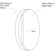
|
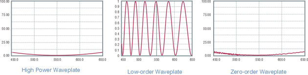
Waveplate Comparison
|
High Power Waveplate
|
Low-order Waveplate
|
Zero-order wavepalte(Cemented/Optical Contacted)
|
|
For Short
|
WPH
|
WPL
|
WPC/WPO
|
|
λ/100Spectra Bandwidth@532nm
|
9.16nm
|
0.51nm
|
9.16nm
|
|
λ/100Temperture Bandwidth△T
|
230.56k
|
12.13k
|
230.56k
|
|
Acceptance Angle
|
11.37°
|
2.63°
|
11.37°
|
|
Damage Threshold@1064nm,10ns,20Hz
|
>10J/cm2
|
>10J/cm2
|
~0.1J/cm2(WPC)
~2J/cm2(WPO)
|
|
Extinction Ratio
|
High
|
High
|
Low
|
|
Quarter Waveplate Part No.
|
Half Waveplate Part No.
|
Diameter
|
|
WPH210Q
|
WPH210H
|
10.0
|
|
WPH212Q
|
WPH212H
|
12.7
|
|
WPH215Q
|
WPH215H
|
15.0
|
|
WPH220Q
|
WPH220H
|
20.0
|
|
WPH225Q
|
WPH225H
|
25.4
|
|
WPH230Q
|
WPH230H
|
30.0
|
Advantages of High Power Waveplate
a.Compare with WPL,WPH has wider spectra&temperature bandwidth and wider angular field.
b. Based on optical bonding,WPH has higher damage threshold and better extinction ratio which compared with WPO or WPC.
c. The thickness of WPH is more suitable for handing compare with single plate true zero order waveplate,which is easy to be damaged.
LOW ORDER WAVEPALTE
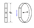
The low order waveplate which can be replaced by mulit-order waveplate is designed to give a retardance of several full waves,plus the desired fraction.This results in a single,physically robust component with desired performance.However,even small varitation in wavelength or temperature will result in significant changes in the desired fraction retardance.
|
Specification
|
|
|
Material
|
Quartz
|
|
Dimension Tolerance
|
+0.0,-0.1
|
|
Wavefront Distortion
|
λ/8@633nm
|
|
Retardation Tolerance
|
λ/60-λ/150(λ<400nm)
λ/150-λ/350(400nm<λ<700nm)
λ/350-λ/600(λ>700nm)
|
|
Parallelism
|
<1 arc second
|
|
Surface Quality
|
20/10scratch /dig
|
|
Clear Apterure
|
Central 90%
|
|
AR Coating
|
<0.2%@wavelength
|
|
Holder
|
Refer to <
|
Standard Wavelength: 266nm, 355nm, 632.8nm, 780nm, 808nm, 980nm, 1064nm, 1310nm, 1550nm
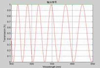
λ/2@532nm λ/4@532nm
Reference product configurations(Without Holder)
|
Quartz Waveplate P/N#
|
Half Waveplate P/N#
|
Diameter(mm)
|
|
WPL210Q
|
WPL210H
|
10.0
|
|
WPL212Q
|
WPL212H
|
12.7
|
|
WPL215Q
|
WPL215H
|
15.0
|
|
WPL220Q
|
WPL220H
|
20.0
|
|
WPL225Q
|
WPL225H
|
25.4
|
|
WPL230Q
|
WPL230H
|
30.0
|
ZERO ORDER WAVEPLATE
The zero order waveplate is designed to give a retardance of zero full waves, plus the desired fraction.Zero order waveplate shows better performance than multiple order wavepalte.It has broad bandwidth and a lower sensitivity to temperature and wavelength changes.It should be considered for more critical applications。
|
Specification
|
|
|
Material
|
Quartz
|
|
Dimension Tolerance
|
+0.0,-0.1
|
|
Wavefront Distortion
|
<λ/8@633nm
|
|
Retardation Tolerance
|
λ/60-λ/150(λ<400nm)
λ/150-λ/350(400nm<λ<700nm)
λ/350-λ/600(λ>700nm)
|
|
Parallelism
|
<1 arc second
|
|
Surface Quality
|
20/10scratch /dig
|
|
Clear Apterure
|
Central 90%
|
|
AR Coating
|
<0.2%@wavelength
|
|
Holder
|
Refer to<
|
StandarWavelength:266nm,355nm,532nm,632.8nm,780nm,808nm,980nm,1064nm,1310nm,1550nm
Note:wavelengths within the range of 240-2300nm are also available upon request.
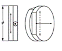
Zero Order Waveplates Optically Contacted
• Optically Contacted
•High Damage Threshold
StandardWavelength:266nm,355nm,532nm,632.8nm,780nm,808nm,850nm,980nm,1064nm,1310nm,1480nm,1550nm
|
Quartz Waveplate P/N#
|
Half Waveplate P/N#
|
Diameter(mm)
|
|
WPO210Q
|
WPO210H
|
10.0
|
|
WPO212Q
|
WPO212H
|
12.7
|
|
WPO215Q
|
WPO215H
|
15.0
|
|
WPO220Q
|
WPO220H
|
20.0
|
|
WPO225Q
|
WPO225H
|
25.4
|
|
WPO230Q
|
WPO230H
|
30.0
|
Zero Order Waveplate Air-spaced Double Retardation Plates
AR Coated,R<0.2% and Mounted
High Damage Threshold
Better Temperature Bandwidth
Wide Wavelength Bandwidth
|
Quartz Waveplates P/N#
|
Half Waveplates P/N#
|
Waveplate Aperture(mm)
|
Mount Diameter(mm)
|
Mount Thickness(mm)
|
|
WPA210Q
|
WPA210H
|
10.0
|
25.4
|
6.0
|
|
WPA212Q
|
WPA212H
|
12.7
|
25.4
|
6.0
|
|
WPA215Q
|
WPA215H
|
15.0
|
25.4
|
6.0
|
|
WPA220Q
|
WPA220H
|
20.0
|
30.0
|
6.0
|
|
WPA225Q
|
WPA225H
|
25.4
|
30.0
|
6.0
|
|
WPA230Q
|
WPA230H
|
30.0
|
38.1
|
6.0
|
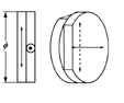
Zero Order Waveplates Cemented by Epoxy
This type of zero order waveplate is constructed of two multiple order waveplate with their axes crossed.Thus the effect of the first plate is canceled by the second ,except for the residual difference between them,
•Cemented by Epoxy
|
Quartz Waveplate P/N#
|
Half Waveplate P/N#
|
Diameter(mm)
|
|
WPC210Q
|
WPC210H
|
10.0
|
|
WPC212Q
|
WPC212H
|
12.7
|
|
WPC215Q
|
WPC215H
|
15.0
|
|
WPC220Q
|
WPC220H
|
20.0
|
|
WPC225Q
|
WPC225H
|
25.4
|
|
WPC230Q
|
WPC230H
|
30.0
|
TRUE ZERO ORDER WAVEPLATE
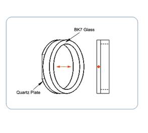
This type of waveplate is constructed of a true zero order waveplate and a BK7 substrate.As the waveplate is very thin and easy to be damaged,the BK7 plates function is to strengthen the wavepalte.
Standard Wavelength:
λ/4:532nm,632.8nm,780nm,808nm,980nm,1064nm,1310nm,1480nm,1550nm
λ/2:532nm,632.8nm,780nm,808nm,980nm,1064nm,1310nm,1480nm,1550nm
|
Quarter Waveplate P/ N#
|
Half Waveplate P/ N#
|
Diameter(mm)
|
|
WPF210Q
|
WPF210H
|
10.0
|
|
WPF212Q
|
WPF212H
|
12.7
|
|
WPF215Q
|
WPF215H
|
15.0
|
|
WPF220Q
|
WPF220H
|
20.0
|
|
WPF225Q
|
WPF225H
|
25.4
|
|
WPF230Q
|
WPF230H
|
30.0
|
True Zero Order Waveplate Single Waveplte
This type of waveplate is made of a very thin quartz waveplate which function as true zero order.In some cases ,the thickness required for single true zero order waveplates is too thin,they have to be provided as first order waveplate.
λ/4: 1310nm, 1480nm, 1550nm
λ/2: 980nm, 1064nm, 1310nm,1480nm, 1550nm
Minimal Thickness:0.038mm
|
Quarter Waveplate P/ N#
|
Half Waveplate P/ N#
|
Diameter(mm)
|
|
WPS210Q
|
WPS210H
|
10.0
|
|
WPS212Q
|
WPS212H
|
12.7
|
|
WPS215Q
|
WPS215H
|
15.0
|
|
WPS220Q
|
WPS220H
|
20.0
|
|
WPS225Q
|
WPS225H
|
25.4
|
|
WPS230Q
|
WPS230H
|
30.0
|
ACHROMATIC WAVEPLATES
Achromatic waveplates combine two birefringent materials, such as quartz and magnesium fluoride. Their different dispersion allows retardance to remain nearly constant over a wider wavelength interval. This differs from a compound zero-order plate made from two sections of the same material.
|
Specification
|
|
|
Material
|
Quartz and MgF2
|
|
Wavefront Distortion
|
λ/8@633nm
|
|
Dimension Tolerance
|
+0.0,-0.1
|
|
Retardation Tolerance
|
λ/100
|
|
Parallelism
|
1 arc second
|
|
Surface Quality
|
40/20 Scratch /Dig
|
|
Clear Apterure
|
Central 90%
|
|
AR Coating
|
Ravg<0.8% at Central Wavelength
|
|
Standard Wavelength
|
VIS 465-650nm,NIR650-1100nm,IR1000-1750m,
|
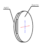
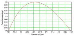
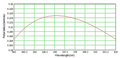
WPBXXXH 465-650nm WPBXXXQ 465-650nm
Achromatic Waveplate Optical Cemented
|
Quartz Waveplate P/N#
|
Half Waveplate P/N#
|
Diameter(mm)
|
|
WPB210Q
|
WPB210H
|
10.0
|
|
WPB212Q
|
WPB212H
|
12.7
|
|
WPB215Q
|
WPB215H
|
15.0
|
|
WPB220Q
|
WPB220H
|
20.0
|
|
WPB225Q
|
WPB225H
|
25.4
|
|
WPB230Q
|
WPB230H
|
30.0
|
Achromatic Waveplate Air-Spaced(Mounted)
|
Quartz Waveplate P/N#
|
Half Waveplate P/N#
|
Waveplate Aperture(mm)
|
Mount Diameter(mm)
|
|
WPB510Q
|
WPB510H
|
10.0
|
12.7
|
|
WPB512Q
|
WPB512H
|
12.7
|
25.4
|
|
WPB515Q
|
WPB515H
|
15.0
|
25.4
|
|
WPB520Q
|
WPB520H
|
20.0
|
25.4
|
|
WPB525Q
|
WPB525H
|
25.4
|
30.0
|
|
WPB530Q
|
WPB530H
|
30.0
|
38.1
|
The WPQ reference design supports a thin true-zero-order quartz plate in an annular glass frame. The beam passes through quartz without epoxy in the optical path. Frame geometry, parallelism and damage resistance depend on the specified assembly.
|
Quarter Waveplate P/ N#
|
Half Waveplate P/ N#
|
Diameter(mm)
|
|
WPQ210Q
|
WPQ210H
|
10.0
|
|
WPQ212Q
|
WPQ212H
|
12.7
|
|
WPQ215Q
|
WPQ215H
|
15.0
|
|
WPQ220Q
|
WPQ220H
|
20.0
|
|
WPQ225Q
|
WPQ225H
|
25.4
|
|
WPQ230Q
|
WPQ230H
|
30.0
|
Double Wavelength Waveplate
Double Wavelength Waveplate is a special kind of multi-order waveplate.It can meet the required retardation at two wavelength at the same time.It widely used to improve the conversion efficiency in solid double frequency laser device.
• Better Parallelism
λ@1064nm+λ/2@532nm,λ/2@1064nm+λ@532nm
λ@532nm+λ/2@355nm, λ/2@532nm+λ@355nm
λ@800nm+λ/2@400nm, λ/2@800nm+λ@400nm
|
P/ N#
|
Diameter(mm)
|
|
WPD210
|
10.0
|
|
WPD212
|
12.7
|
|
WPD215
|
15.0
|
|
WPD220
|
20.0
|
|
WPD225
|
25.4
|
|
WPD230
|
30.0
|
Equation note: the legacy expression neno is ambiguous. Retardance is interpreted as δ = 2πd(nₑ − nₒ)/λ; the original expression remains above for traceability.
