

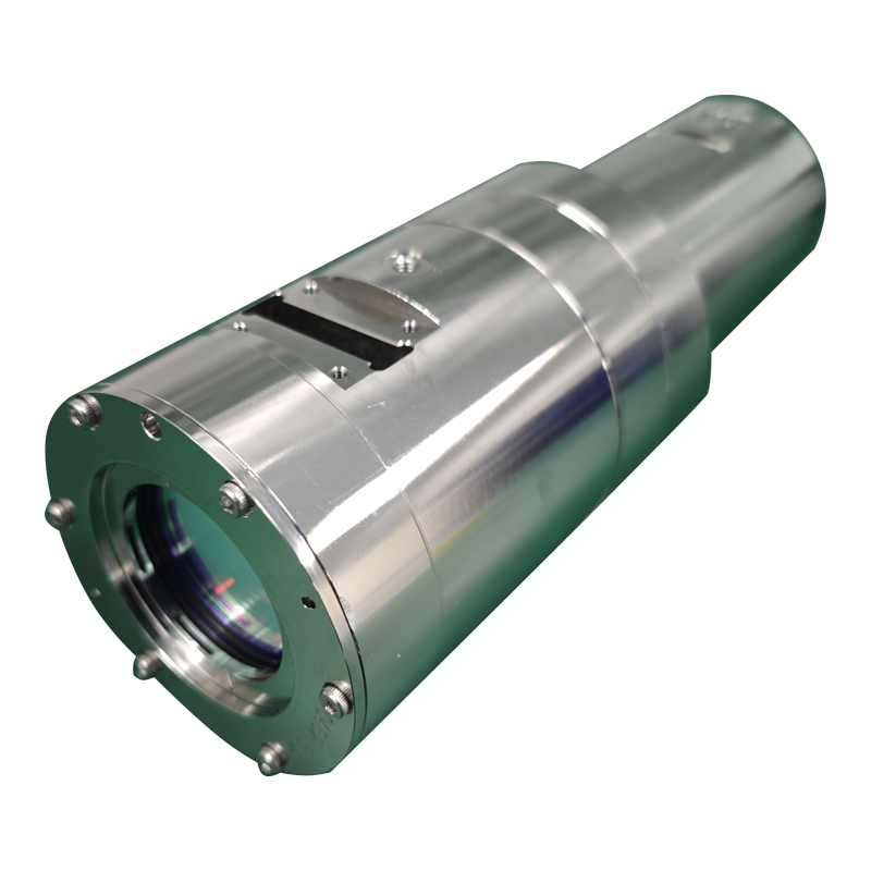
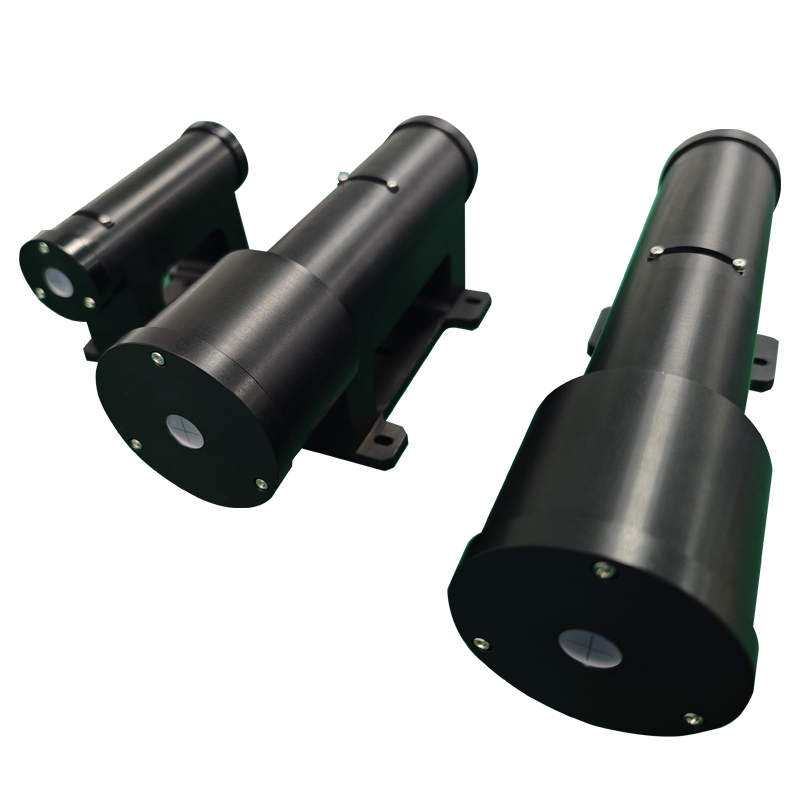
A diode-pumped solid-state (DPSS) laser combines pump delivery, a solid-state gain medium and a resonator. Nonlinear crystals can then convert the laser wavelength, while a Q-switch can change the temporal operating regime. Understanding the role of each stage is more useful than treating a layout drawing as a complete build specification.
The examples below describe historical reference architectures. Their wavelengths and power labels explain the optical arrangements; they are not offered-product ratings, verified performance measurements or customer installations. Mirror coatings, dimensions, pump conditions and thermal design must still be specified for an actual laser.
The basic optical chain
Pump optics deliver diode light to the gain medium. A resonator provides feedback at the selected laser wavelength. Intracavity components can control polarization, pulse formation or nonlinear conversion. Output coupling then extracts the desired wavelength. A converted-output system may contain more than one resonant or single-pass stage, so the path of each wavelength should be traced separately.
Eight representative arrangements
1. Continuous-wave blue generation from Nd:YAG
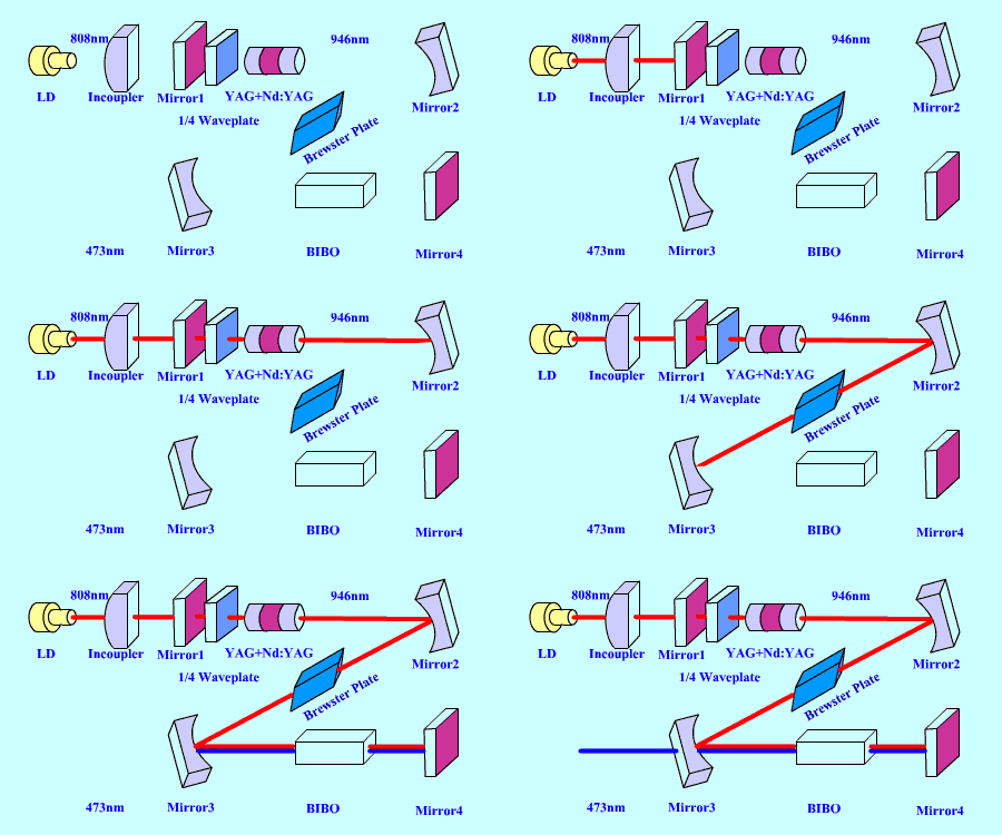
The blue reference uses an 808 nm diode pump and a YAG + Nd:YAG gain assembly, with a folded mirror path, a quarter-wave plate, a Brewster plate and a BiBO nonlinear crystal. The fundamental is labeled 946 nm, and its second harmonic is 473 nm. The relationship is 946 nm / 2 = 473 nm.
The original layout carries a 2.8 W blue-output label. This is a historical example value, not a general capability of Nd:YAG or a specification for a current laser. The distinct 946 nm transition and the resonator’s wavelength selection are essential to interpreting this example; it should not be read as ordinary 1064 nm doubling.
2. Continuous-wave green generation from Nd:YAG
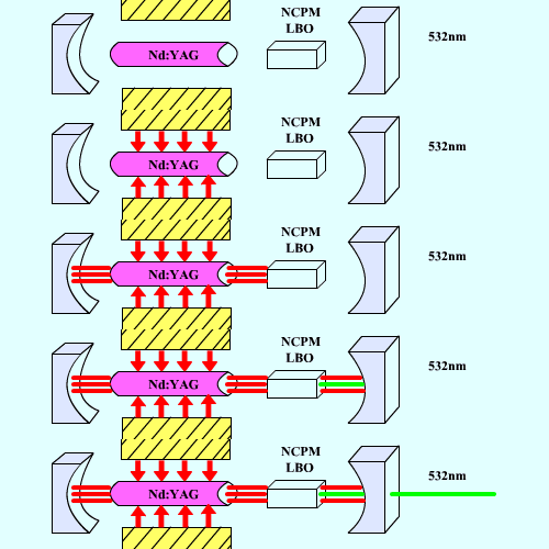
A second arrangement places an Nd:YAG rod and an LBO crystal between resonator mirrors. The LBO is labeled NCPM, meaning noncritical phase matching, and the output is 532 nm. The optical idea is intracavity doubling of the Nd:YAG fundamental. The pump is drawn alongside the rod rather than as the end-pump train of the blue example.
3. Continuous-wave green generation from Nd:YVO4
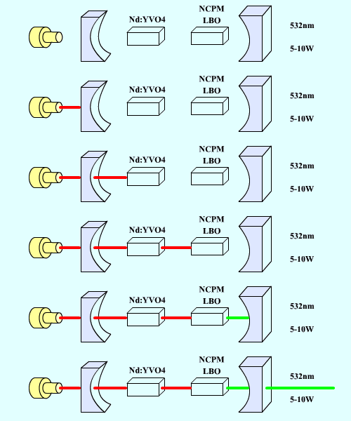
An end-pumped Nd:YVO4 layout also uses an NCPM LBO stage and a 532 nm output. The source drawing labels a 5–10 W range. Treat that range as a reference annotation requiring its own operating conditions, rather than a prediction from the gain-material name. Nd:YVO4 and Nd:YAG layouts must each be designed around their gain and thermal behavior.
4. Q-switched green generation from Nd:YAG
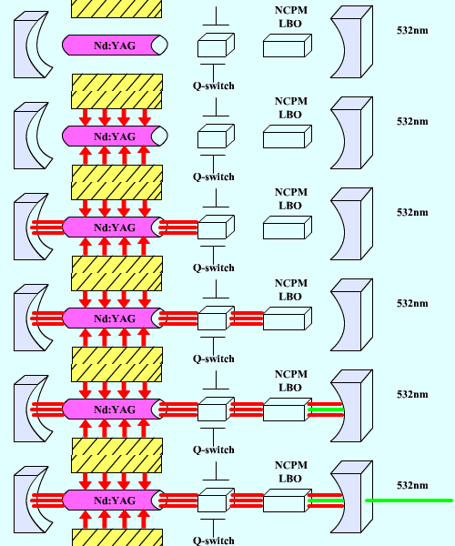
The pulsed green arrangement adds a Q-switch to the Nd:YAG resonator before the NCPM LBO stage. The Q-switch changes the resonator loss in time so that energy can accumulate and be released in a pulse. The conversion target remains 532 nm, but pulse energy, duration and repetition rate become important design quantities alongside average power.
5. Pulsed ultraviolet generation with two conversion stages
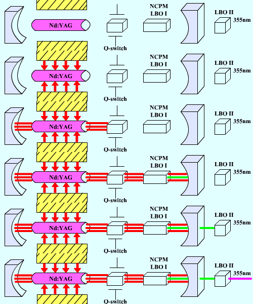
The ultraviolet arrangement contains Nd:YAG, a Q-switch and two LBO stages labeled LBO I and LBO II. The first conversion stage provides the second harmonic; the second mixes the appropriate fundamental and harmonic fields to generate approximately 355 nm. This is the familiar third-harmonic chain: 1064 nm → 532 nm, followed by 1064 nm + 532 nm → 355 nm.
The drawing places the second LBO outside the main resonator mirror. This distinction matters: the two crystals are different stages with different incident wavelength combinations, rather than two interchangeable doubling crystals in series.
6. Short-pulse blue generation from Ti:sapphire
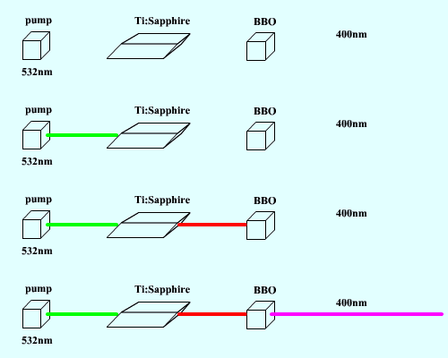
A separate reference chain labels a 532 nm pump, a Ti:sapphire stage and a BBO crystal producing 400 nm. The blue output is consistent with doubling a fundamental near 800 nm. The source labels this an ultrafast-pulse arrangement, but supplies no pulse duration, dispersion compensation or mode-locking implementation. The block sequence therefore illustrates wavelength conversion, without specifying a complete ultrafast resonator.
7. Nd:YAG-driven optical parametric generation
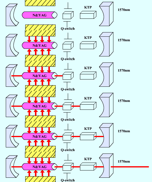
The parametric example shows an Nd:YAG laser, Q-switch and KTP element, with a generated wavelength labeled 1570 nm. An OPO converts pump energy into signal and idler fields subject to 1/λp = 1/λs + 1/λi. The second generated wavelength is not labeled in the reference, and no numerical idler specification is inferred here. The crystal and resonator must support the intended parametric interaction.
8. Zigzag solid-state laser geometry
The final sketch uses a slab-like zigzag gain geometry, labeled for Nd:YAG or Nd:YVO4, with 1064 nm output. This is a gain-path architecture rather than a separate nonlinear conversion process. Its pump arrangement, resonator optics and heat removal must be evaluated together; the schematic alone does not establish a power rating or beam-quality result.

Comparing the design choices
| Desired behavior | Key components | Question to resolve |
|---|---|---|
| Continuous-wave visible output | Gain medium, resonator and intracavity nonlinear crystal | Which fundamental transition and phase-matching arrangement produce the required color? |
| Pulsed green or ultraviolet output | Q-switch and one or two conversion stages | What pulse conditions reach each crystal, and how are the residual wavelengths handled? |
| Short-pulse blue output | Ti:sapphire source and BBO stage | What pulse formation and dispersion controls are required beyond the wavelength blocks? |
| Parametric output | Pump laser, KTP and parametric feedback arrangement | Which signal–idler pair is phase matched and resonated? |
| Zigzag gain path | Slab gain medium, pump and resonator | How do the gain path and thermal conditions determine useful output? |
Before converting any reference architecture into a hardware design, establish the pump wavelength and geometry, fundamental wavelength, temporal regime, desired output and conversion-crystal operating condition. Then define the mirror behavior at every wavelength present. These steps turn a conceptual chain into a set of optical requirements without relying on an unlabeled drawing or a historical output-power annotation.
