

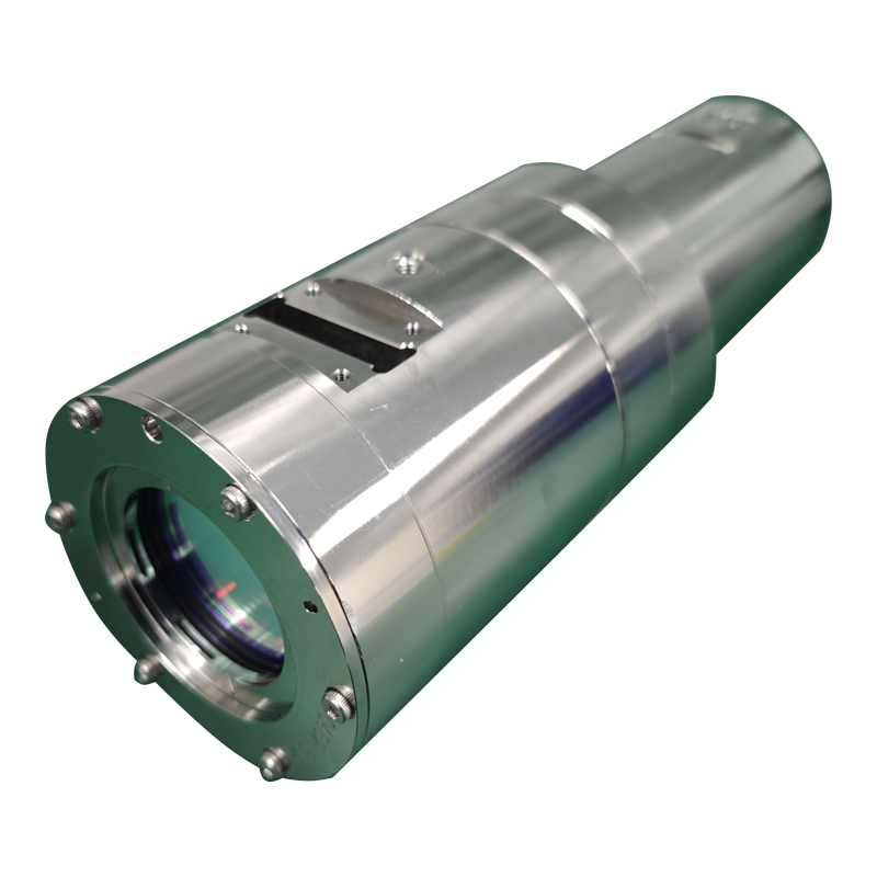
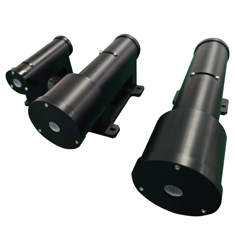
An optical isolator reduces the amount of reflected light returning toward a laser. Feedback can disturb the laser frequency, increase amplitude fluctuations and noise, or limit modulation performance. In some systems, sufficiently strong feedback can also contribute to damage. A Faraday isolator makes the forward and return paths behave differently by using nonreciprocal polarization rotation.
The three essential elements
- Input polarizer: selects a linear polarization direction, used here as the 0° reference.
- Faraday rotator: a magneto-optic element in a magnetic field, arranged to rotate the polarization by 45° at its design operating condition.
- Output polarizer or analyzer: has its transmission axis at 45° relative to the input polarizer.
The angles refer to the polarization axes of an idealized single-stage isolator. Actual devices have wavelength and operating-condition limits. The simple model explains the mechanism without assuming that a real device has zero loss or infinite isolation.
Forward propagation
The incident beam first encounters the input polarizer. If its polarization already agrees with the transmission axis, that component is passed. If the incident light is unpolarized or differently polarized, the polarizer selects the allowed component rather than transmitting all incident power.
The linearly polarized transmitted beam enters the Faraday material. A 45° rotation places its polarization parallel to the output analyzer. In the ideal model it therefore passes the analyzer and travels to the downstream optics. A reflection from a downstream surface can then send some light back toward the isolator.
Reverse propagation
The reflected light reaches the output analyzer first. The analyzer transmits only the component along its 45° axis. This return component then traverses the Faraday rotator.
The crucial property is nonreciprocity: on retracing the optical path, the Faraday rotation does not undo the first rotation as a reciprocal polarization rotation would. In a consistent fixed reference convention, the return polarization acquires another 45° rotation. It is now at 90° to the input polarizer’s transmission axis, so the ideal input polarizer rejects it.
| Direction | First polarizer | After Faraday rotation | Final polarizer |
|---|---|---|---|
| Forward | Input axis: 0° | 45° | Output axis: 45°; transmitted |
| Reverse | Output axis: 45° | 90° relative to the input axis | Input axis: 0°; rejected |
Why alignment and operating wavelength matter
The rejection mechanism depends on the polarization arriving at the input polarizer being perpendicular to its transmission axis. If the rotator does not provide its intended rotation, or if the polarizer axes are misaligned, some return light can pass. Consequently the design wavelength and the actual polarization state are part of the system specification, alongside forward transmission.
It is also useful to distinguish the laser beam from the reflected beam. Good forward transmission shows that the desired beam passes through the instrument; it does not by itself measure how well feedback is rejected. The relevant reverse condition must be considered separately.
Applying the principle in a laser system
Place the isolator so that reflections from the downstream optical train encounter the output side on their return. Align its input polarization with the laser when the device requires a linearly polarized input. Then check the specified operating wavelength, forward transmission and reverse isolation for the intended setup. The purpose is controlled feedback suppression; the idealized statement that light passes in one direction only is a description of the mechanism, rather than an absolute claim about every real isolator.
